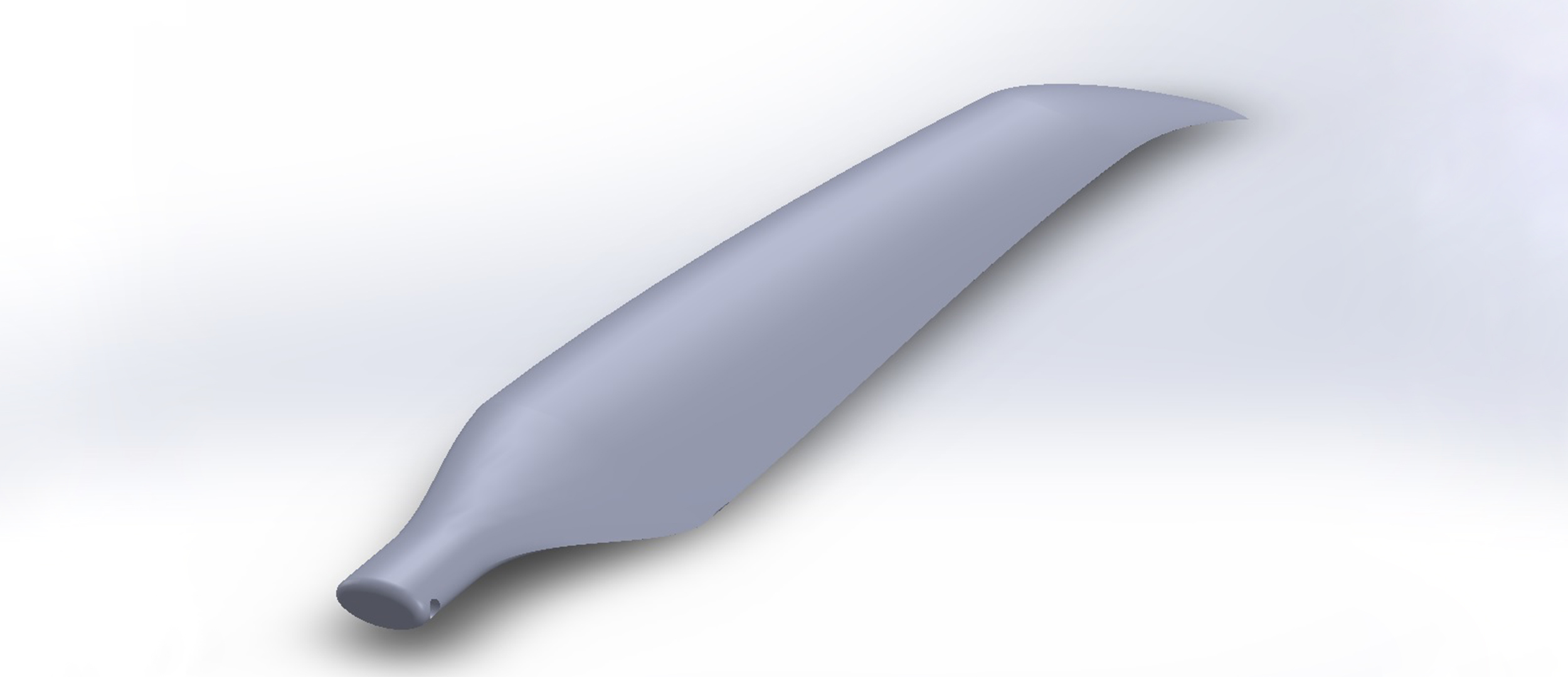
Closing propeller for electric paramotor
Attention! The following description is intended to showcase the manufacturing technology involved! A propeller can be extremely dangerous if someone attempts to create it without the necessary expertise and experience! The author of the post does not recommend that anyone attempt to create a propeller based on the information provided without sufficient professional knowledge and practice!
For a long time, I have been involved in making propellers for paragliding back motors, primarily for personal use. Copying modifications of initial factory propellers has now been replaced by entirely self-designed ones. I believe that making a propeller from composite materials is one of the most challenging areas from every aspect.
The surface has a complicated, three-dimensional curvature, and creating a template for it is a serious task. If the template is successful, then creating the propeller in a way that can withstand the enormous forces (sometimes tons) while not being too heavy...that's where the challenge lies.

As 3D printing became more widespread, it was obvious to me that I would apply it in this field as well.
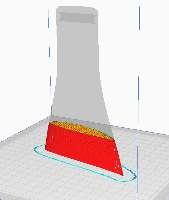
Using the main parameters determined beforehand on paper (diameter, profile, lift, etc.), the 3D model of the propeller must first be created in a CAD software. A good design program (e.g. Solidworks) not only assists in creating the model, but also allows us to see the main aerodynamic characteristics before we have even manufactured the first prototype. This is where various flow simulation models (e.g. Solidworks Flow Simulation) come into play.
Even if we do not use a flow simulation model, CAD-supported design is still a great help and also necessary for 3D printing. The propeller model created in the model space is converted into the software necessary for 3D printing, where the gcode used by the printer is written.
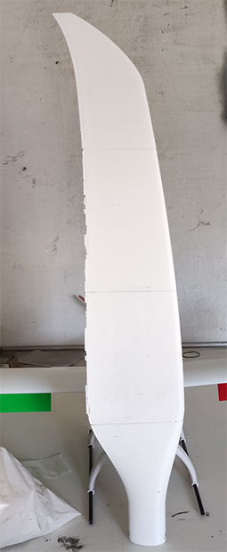
With the finished gcode, the actual implementation could begin, starting with printing out the original sample of the propeller. The printed sample alone is not suitable for creating a negative form, so surface treatment and quality improvement are necessary.
There are various options for this, in this case, I used two-component filler and varnish.

From the finished original sample, a heat-resistant epoxy resin-based negative form was made. This is somewhat more expensive than if it were made of polyester, but in the long run, my goal was to not only make the propeller using a "traditional" method, but also from carbon fiber prepreg.
I will write more about prepreg technology in another post, but for now, it is enough to know that high temperatures (from 85 to 120 degrees Celsius) are required for the process. Therefore, the negative form designed for this technology must be resistant to high temperatures.
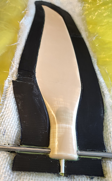
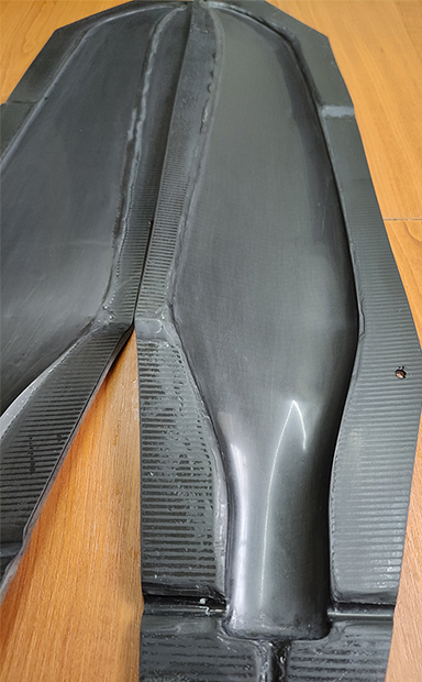
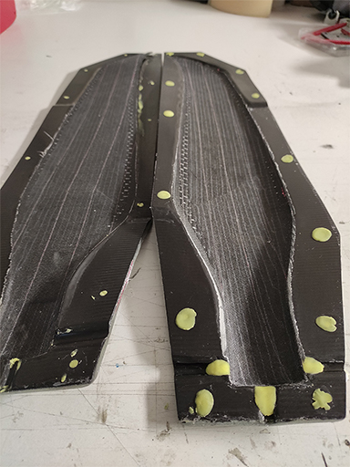
The two halves of the propeller are produced in the finished mold using pre-impregnated carbon fiber layers. The mold, lined with laminated layers, is first placed in a vacuum bag and then into an autoclave under pressure. This process minimizes defects between the carbon fiber layers and removes excess resin, reducing the weight of the final product while increasing its load capacity.
The halves are then glued together and partially filled with foaming epoxy resin to maintain structural stability. The propeller blade rotates around a steel pivot during operation. Direct contact between the steel pivot and the carbon fiber structure would cause the steel to wear out quickly, so a titanium tube was incorporated to serve as a passageway for the steel pivot. The use of titanium serves two purposes: it minimizes weight and prevents galvanic corrosion.
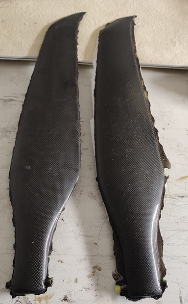
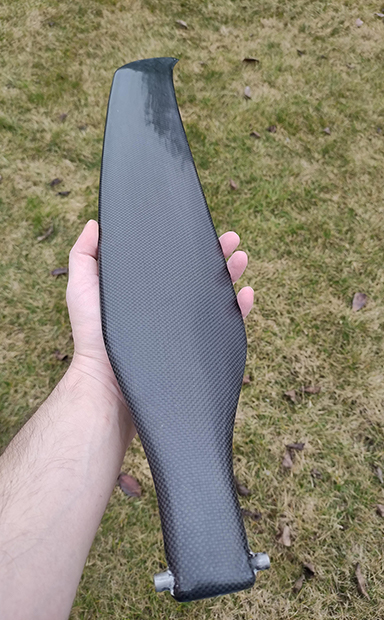
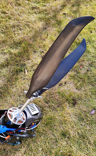
After balancing and surface treatment, the finished propeller blades were assembled and ready for use. Testing has not yet been conducted, and the results will be reported in a separate post.

